Due to the unavailability of some through hole components, this project is now obsolete, but is still published so that those who built it (around 800 people) have a hard record of technical details for reference.
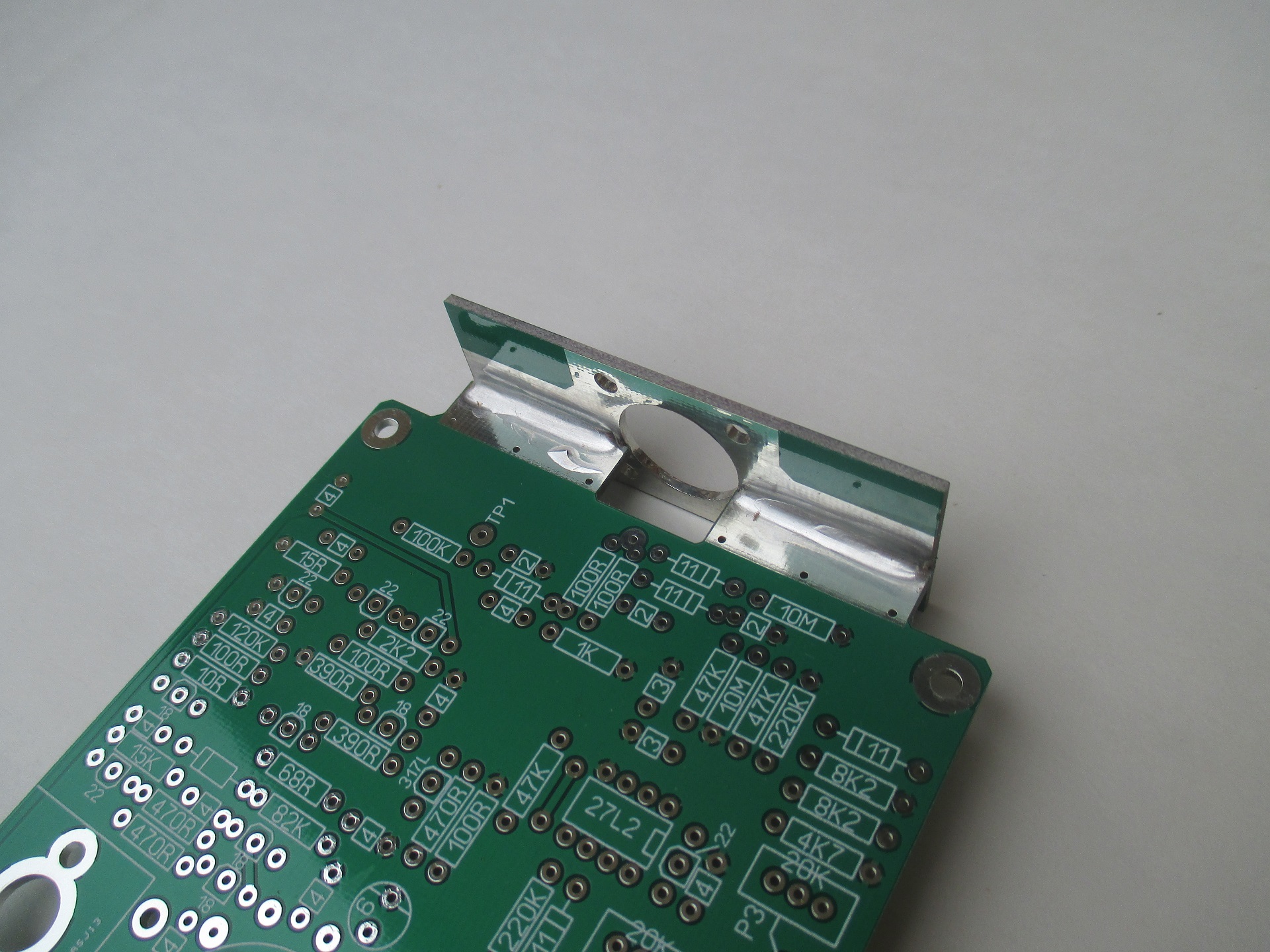
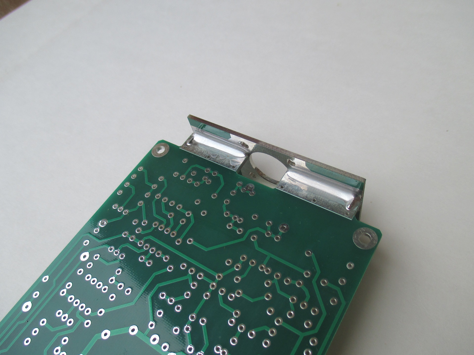
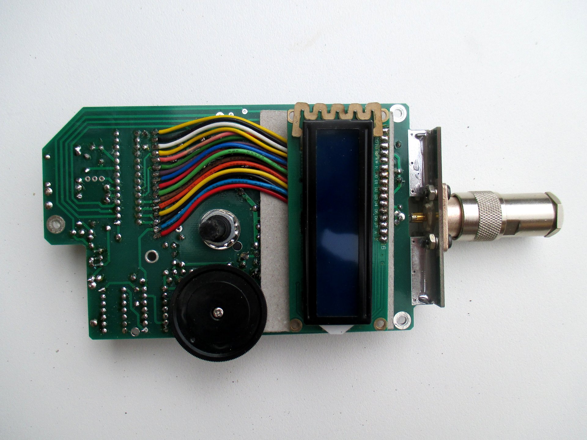
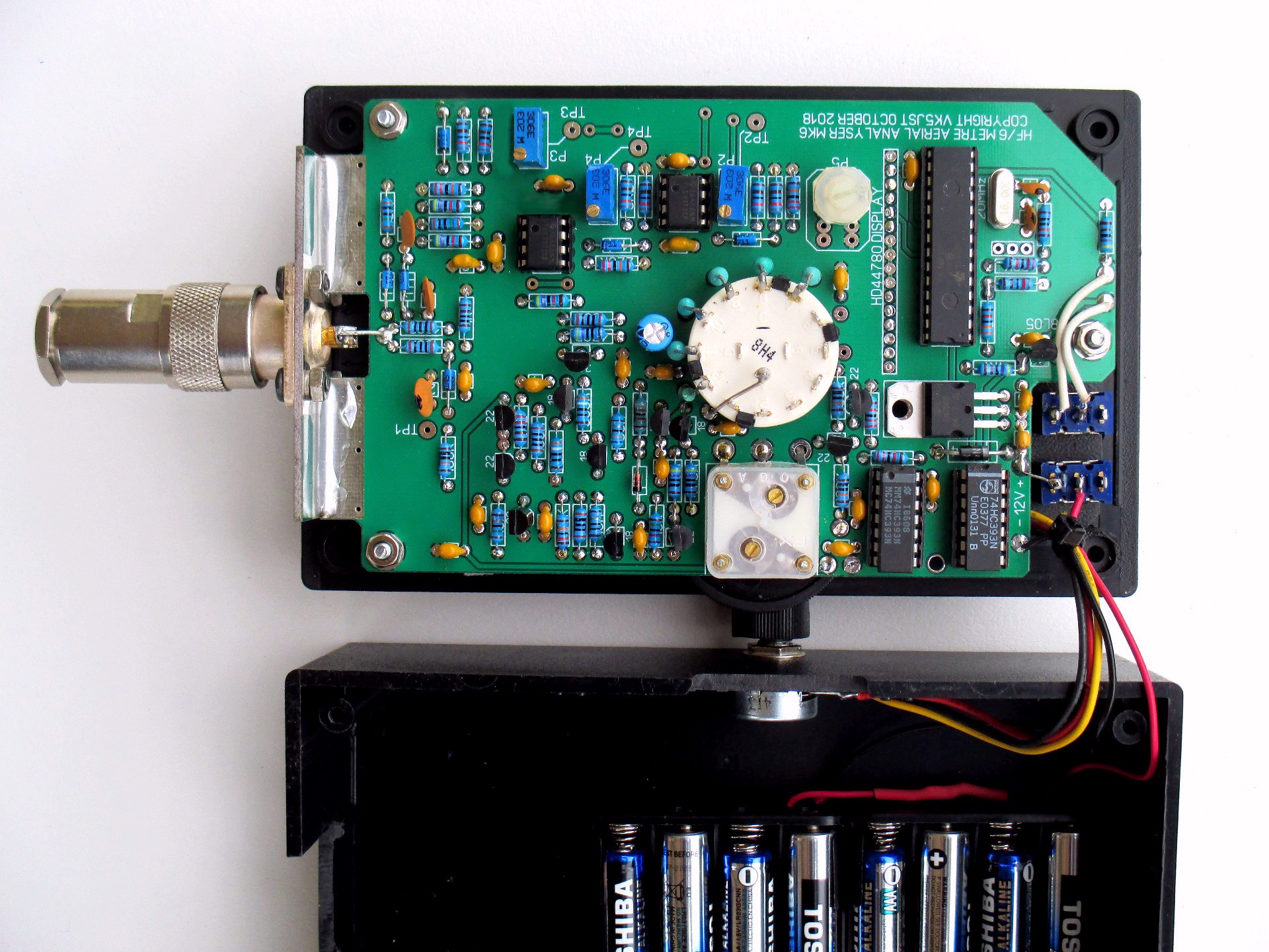
Two photos showing the front and back of the main PCB when the Connector PCB has been attached with solder.
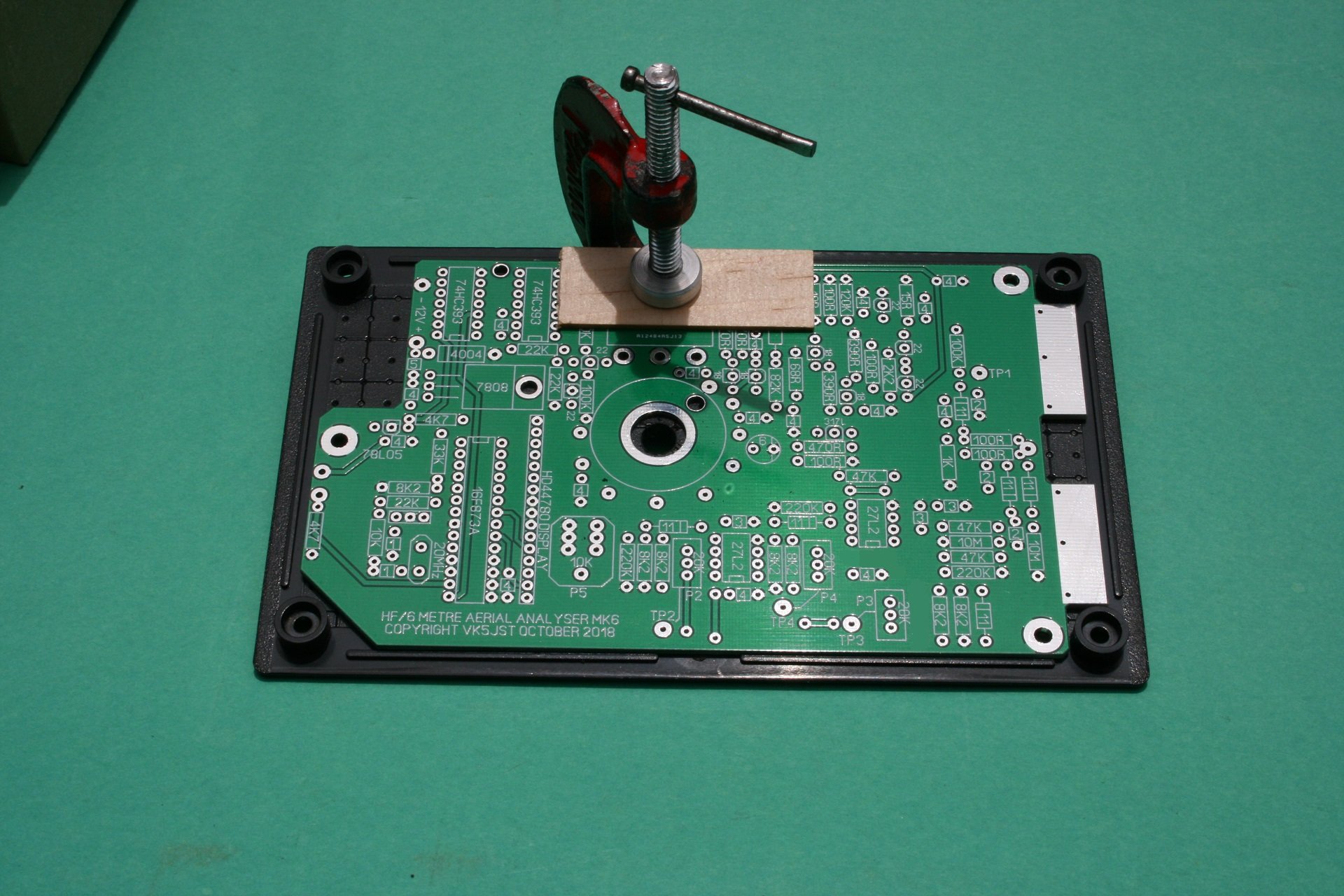
Using the Main PCB to drill the box lid.......... Note the careful centralising of the PCB, both horizontally and vertically, achieved by using the ridges provided just inside the edge of the box lid.
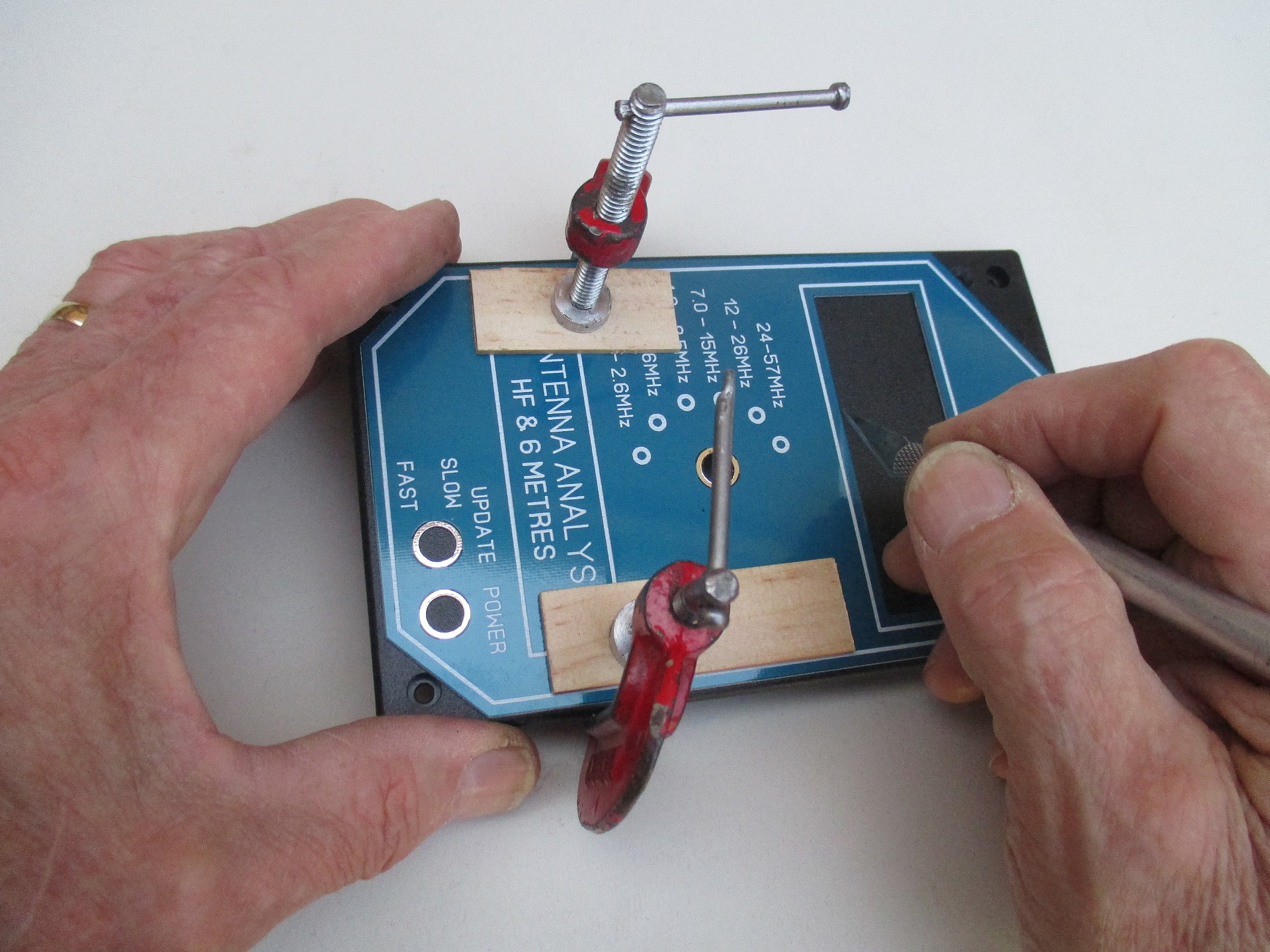
Using the Front Panel to Mark out the LCD Hole and 2 switch holes in the box lid.........Use the hole previously drilled in the lid top for the rotary switch shaft to accurately position the front panel.
Attaching The LCD to the main PCB..........This is the simplest way, but plugs and sockets are another method which can be used by constructors. Note the clip-on spacer on the front of the LCD, which ensures the LCD sits flat against the rear of the box lid. Also note the elephant hide insulation behind the LCD, ensuring that no contact can be made with the main pcb rear.
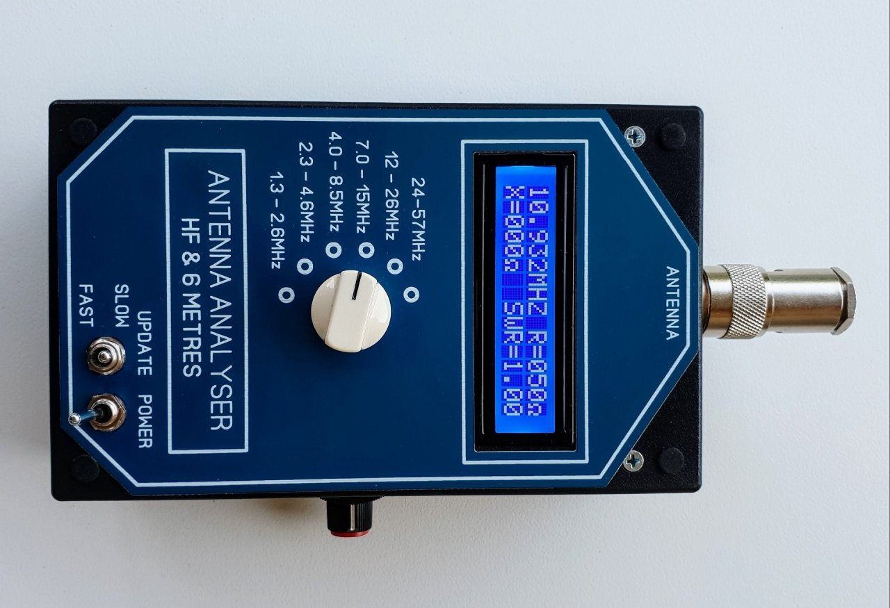
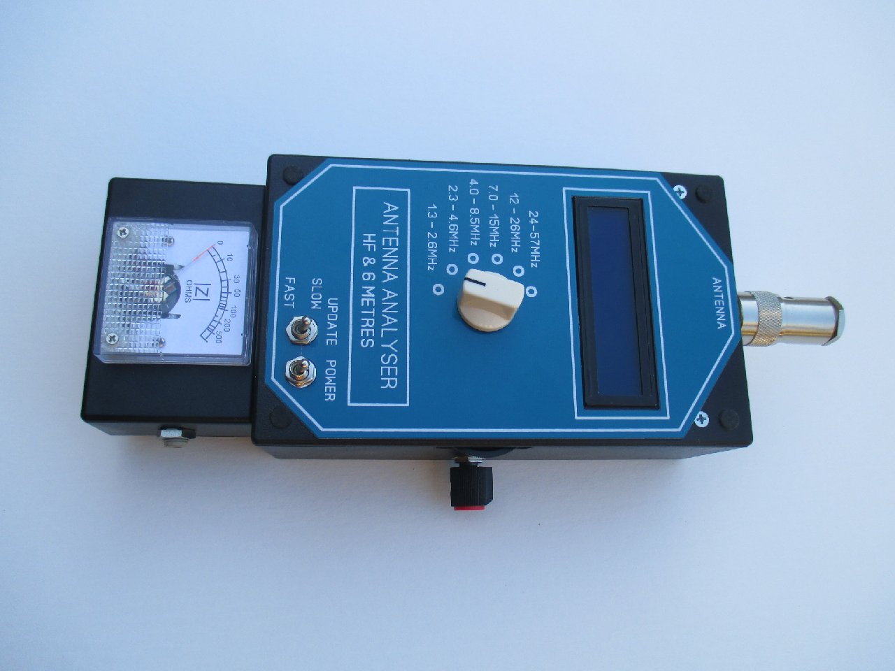
An internal view of the completed analyser